

Inergen®- IG541
Inergen®- IG541
Known as being an inert gas, Inergen® is a patented air mixture which comprises of N₂/AR/CO₂. Inergen® extinguishing principle works behind replacement of oxygen within a protected area.
This means that the oxygen content in the atmosphere at sea level, is 20.9%. If this oxygen is lowered to somewhere between 10-14%, most common fires will be extinguished. Where other extinguishing agents just lower the oxygen level, Inergen®- IG541 distinguishes itself by maintaining an oxygen level which ensures area to remain occupied. Inergen®- IG541 systems are available in various size of cylinders to offer different levels of gas concentration. Systems can be installed as Pre-Engineered solutions using modular cylinders or engineered using distributed pipe works to carry the gas from the cylinder(s) and distribute it evenly through the calibrated nozzle(s) in the room, ceiling as well as floor voids; which under both scenarios shall provide total flooding with 3D extinguishing effect. This means that even hidden fires can be quickly and effectively extinguished.
Why use Inergen®- IG541?
Extinguishes fires quickly. When released, Inergen®- IG541 lowers the room temperature and reduces the oxygen level, preventing overheating and re-ignition.
Puts out fires for good
Harmless to people and equipment
Prevents secondary damage
Can be tailored to specific requirements
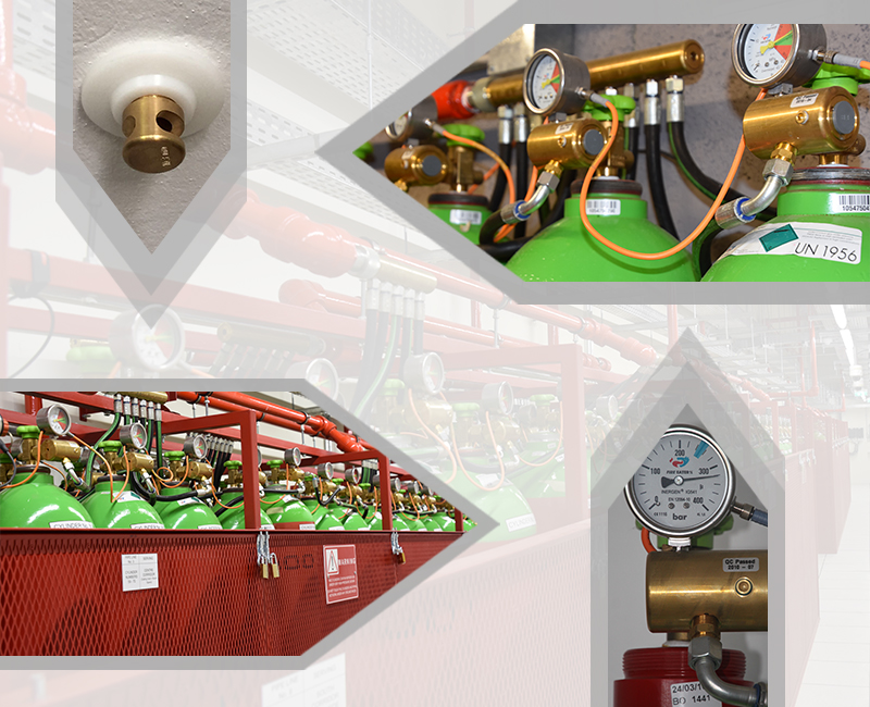
Characteristics of cylinders and pipeworks:
High Pressure Cylinders are used on Inergen®- IG541 Installations. Cylinders are under a pressure of 200 to 300 BAR. The high gas compression ratio means fewer cylinders and valves, resulting in cost and space savings. Cylinders are equipped with standard threaded valves. Gas is stored at 200 or 300 BAR and reduced to a working pressure of 60 BAR when released. Inergen®- IG541 cylinders are equipped with a manometer which shows whether the cylinders are pressurized or not. Each Engineered system is designed around the parameters and risks associated to the protected area. Pipe works are seamless ASTM grade for high pressure systems and fittings are NPT threaded, forged to ASTM A182 – ANSI Standards 3000Lbs. Nozzles are made of brass and designed to control the flow using a single orifice with dimensions that vary with respect to the discharge rate per nozzle defined under the design calculations. Reference of Standards used: SANS 14520, ISO 14520 & NFPA 2001
Room integrity test
It is a requirement to have a gas protected area subject to a Room Integrity Test. A specialized door fan equipment is used to perform the exercise which is required to measure retention hold time of a gas protected area allowing one to assess whether or not, there is any significant leakage that will affect the efficiency of the suppression system. It also allows to establish the size of any pressure relief vent required when using a high pressure system such as Inergen®- IG541. We, at Vitech Electronics, are equipped with such test equipment and tests conducted are supported by software generated reports.
Inert Gases vs Halocarbons
Both Gases are clean non-conductive and require no clean up following a discharge. Vitech Electronics Ltd supplies both products and each product has it merits as well as shortcomings. In this case we have considered all the aspect of protecting the risks and providing the client with the best option for their application. For this we considered the size of the areas being protected, the logistics of pressure venting, pipe work, foot print and installation.
What is an Inert Gas?
An inert gas is a natural gas present in our atmosphere. Inert gas extinguish fires by reducing the oxygen in the area to below 15% were fires cannot continue to burn, but allow safe exposure for people who may be inside the areas during discharge.
Pro’s
Inert gases don’t break down when extinguishing a fire.
Cylinders can be positioned far away from the risk.
Agent is cheaper to refill than a halocarbon
Pipe network can be more forgiving and more nozzles can be installed to protect areas
Using Selector valves, Inergen®- IG541 systems can protect multiple areas from one bank.
Extended discharge.
Good gas retention times.
Con's
High pressure system, require heaver engineering, heaver duty pipe work and skills to install.
Although 300bar systems take up little floor space. Floor loading can sometimes be an issue on very large systems.
Inert Gases - design parameters
Concentration: 38% Class A
Ozone depletion: 0
Global Warming: 0
Discharge time: 60 Seconds
Applications : Electrical, Data processing, Strong rooms, Archives
Approval: NFPA2001; ISO14250; UL; VDS; FM; LPCB
What is a Halocarbon Gas?
Halocarbons such as HFC227 (FM200®) are chemical gases produced by leading chemical companies such as Dupont and Great lakes. These are CLEAN AGENTS suitable for most applications. FM200® extinguishes fires by removing the heat element and reacting with the combustion process. The gas is stored at a lower pressure and only requires a design concentration of 7.9% suitable for occupied areas.
Pro’s
Easy to install.
Pre-engineered and limited pipe networks work.
Small foot print.
Lower weight
Quick to refill
Easy to modify
Con's
Costly to refill.
Breaks down to Hydrogen fluorides in small quantities when extinguishing fire.
Cannot support complicated and long distance pipe runs.
FM200® (HFC227) - design parameter
Concentration: 7.9% Class A
Ozone depletion: 0
Global warming: 2900
Discharge time: 10 seconds
Applications : Electrical, Data processing, Strong rooms, Archives
Approval: NFPA2001; ISO14250; UL; TUV VDS; FM; LPCB
Storage + piping requirements!
Halocarbon gases like FM200® only require 7.9% concentration to extinguish a fire; hence this gas can be housed in far fewer cylinders than inert gases, Because of this it is possible to place the cylinders inside the risk. Inert gases will require a far greater foot print (storage) and it is not common practice to Installing inert gas cylinders in the risk as this will reduce the floor space substantially. In most cases inert gas cylinders are housed in a separate room and because of the high pressures it is possible to pipe this gas into the risk. However the pipe work used must be Schedule 80 to shed 40 with fitting rated to 3000 psi.
Venting requirements for FM200® systems
Unlike the inert gas where large volumes of air within the risk are displaced by the suppression system reducing oxygen to extinguish fires. For example, in an Inert gas application up to 45% of the total volume of normal air is replace with a mixture of Nitrogen and Argon @ 200bar. The processes reduces oxygen content to below what is require for combustion and above the minimum oxygen requirements for humans to remain safely in the area for up to 5 minutes. On Inert gas discharge large volumes of normal air have to leave the protected area within 60seconds. The industry makes use of an over pressurization vent which open under predetermined force to allow air to move from INSIDE the risk to the OUTSIDE without damaging any structure.
FM200® and other chemical gasses work on replacing the heat element in the combustion process. Hence, the required gas to extinguish the same area is less that 10% of total volume of the risk at 25bar. The low gas concentrations drastically reduce the requirements of an over pressurization vent.
Venting in an FM200®application is not normally an issue provided your wall strength is more that 1.5-2 lbs per Square Foot. However in both applications it is important to ensure that area utilizing Gas suppression systems are in fact suited for the agent including sufficient wall strength and gas retention hold times.
Discharge test
There are two main standards used to design and install FM200®systems. IS014520 or the NFPA2000. Both standards are similar as far as final designs are concerned and achieve the same results for fire suppression. None of the above standards request a discharge test to be done on FM200®.
There is no clear winner. Both gases will meet the requirement of extinguishing fires
Detection
Fire Suppression systems are normally coupled with an early warning detection system comprising of but not limited to:
A gas extinguishing Control Panel with battery back-up- Automatic/manual mode switching and a gas release call point.
Smoke or combined smoke detection depending on the nature of the risk.
Audible & Visual Alarms
Visual door warning indicators
Abort Facility
Relays as may be found required
The early warning detection should be arranged that there will be both a primary and secondary sequence known as a double knock of audible and visual alarms prior to the activation of a pre-set extinguishing time delay of between 30-60 seconds. Systems shall provide double-knock to provide two stage alerts whereby detectors shall, in that respect, be wired onto two different circuits (2 Zones) within the gas protected area.
A typical Scenario:
First Stage Alarm – Alarm Bell and any optional visual indicator are energized. Auxiliary contacts are activated to perform system functions such as: operate door holders/closures on access doors, transmit signal to main fire Alarm system, shut down of HVAC equipment.
Second Stage Alarm –
Alarm Sounder and any optional visual indicator are energized.
HVAC system is shut down/ dampers closed.
Gas Release delay sequence is started
Completion of Time delay sequence –
Gas is released
Door warning visual indicators are on within and outside the hazard in which the discharge is occurring